Got a wild hair yesterday and decided to go out to the shop and look for materials to attempt a Helix antenna.
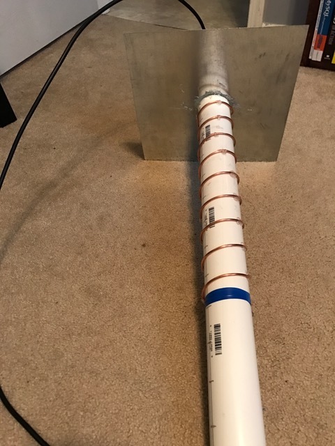
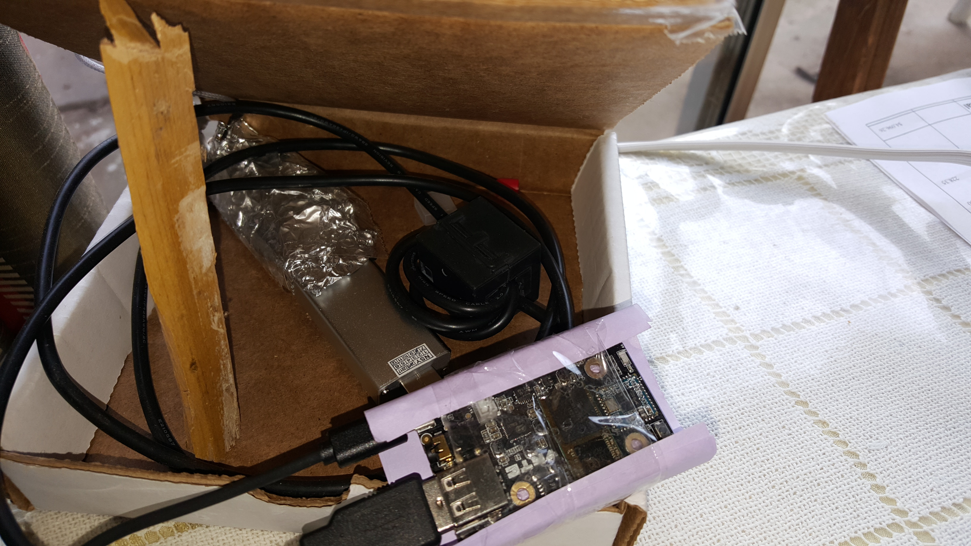
fired up the calculator and started building. Here is what I came up with real quick.
As you can see it is not very pretty.
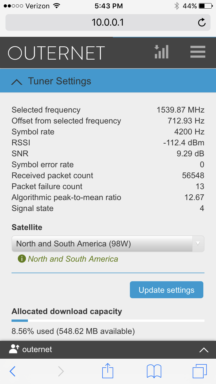
I didnt have the SMA bulkhead connector that I wanted to use so I used the only thing I had. an SO-239 with the mating PL-259 coming out of the back of the antenna. Had 3 foot of junk coax on hand and had to use that as well. So all in all there are 4 adapters in line between the LNA and the antenna. And crappy coax. Disconnected the Panel antenna that comes with the kit and put this one inline. It has a beamwidth of about 24 degrees so its a bit more precise of an aiming experiment than the fantastic antenna that comes with the DIY kit. Having said that, I did not spend a lot of time aiming precisely. plugged it in and aimed it in the general direction of the satellite. Here are the results from the OUTERNET UI.
Side note: the refresh on the UI lagged a bit so it was hard to get a good idea of when I was actually pointed in an optimal direction but it worked good enough.
Yes sir its 9 turns. my connectors and cable choice are degrading this by about 3dB. the SNR of the kit panel in the same spot was average 5-7 db. (These readings were while on the RPI micro controller. They differ greatly on the CHIP with Skylark.) After the move to Skylark on the CHIP I am lucky if I get 3-4db and the RSSI is a lot worse. I assume it is due to noise but have not tracked it down yet. I believe the CHIP is somewhat susceptible to the noise of my Powered USB in the box with it.
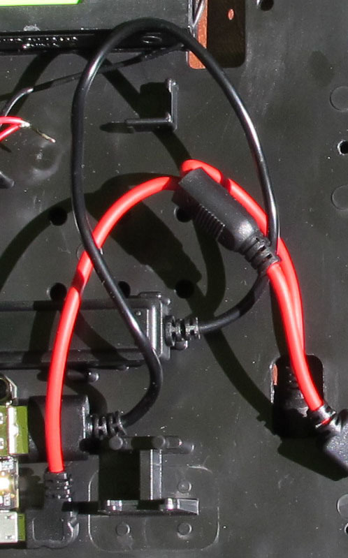
@ki4its I found that the USB on the CHIP was just a giant noise source. I didn’t put a spectrum analyzer on it but when I added a 3ft USB A-B extension wound three turns on a snap on core it really choked the noise off in the receiver. I was having issues getting a lock with the patch antenna and SNR in the 2-3 range, after the hack I am getting 6-7 SNR in the same spot indoors looking through a window. I had tried several USB power connectors including a true apple part and it did not make any difference.
I also did a quick and dirty shielding job on the PA. 2-3 wraps in packing tape and bubble wrap then covered the whole mess in two layers of thick Al foil. I thought of doing the same thing with the CHIP but I was holding off until I am sure Skylark is stable.
-Cecil
AA5CE
PS Did you use an online calc, or just the ARRL antenna book?
Smart move on the ferrite. I had planned to use a 6" USB cable just to keep the SDR heat away from the CHIP. Will add a ferrite also. I have a SDRPlay that I have copper foiled the case and added ferrites to the USB cable and really simmered down the noise.
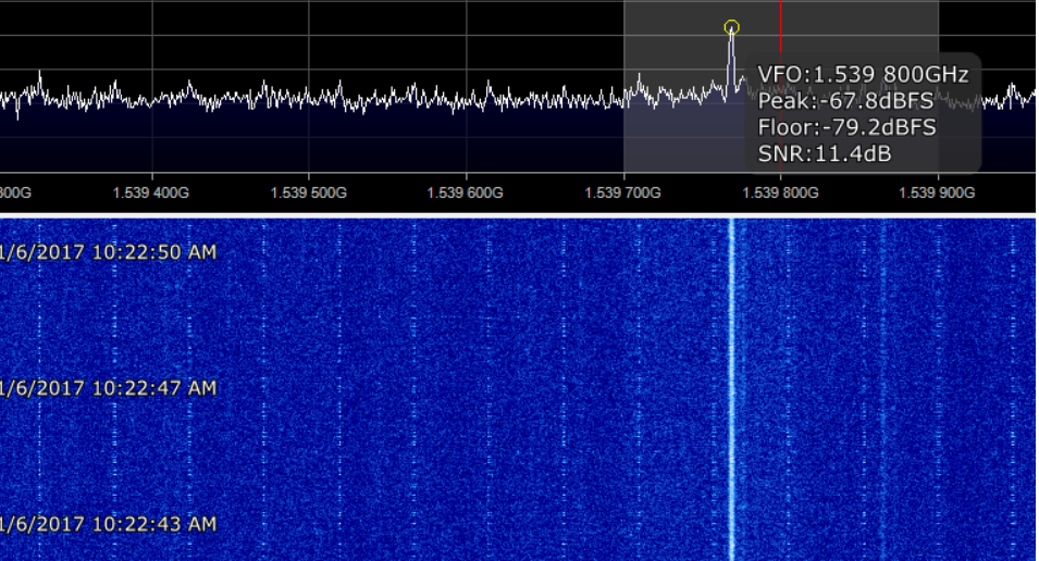
Quick screenshot of the SNR of this antenna without the LNA attached. The results fall in line with what the design calculator stated I should achieve. I need to tune the spacing of the coils to get it better. (and put it on a good mount. I was holding it in my hand for these readings)
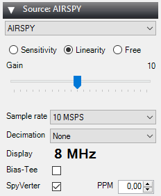
setup was SDR# with an AIRSPY SDR attached directly to the antenna connector. No adapters or coax.
I will do it again later with the LNA inline.
Oh - - OK. I was looking at the solution backwards. In the Alpha Lantern, I would put the core on the pigtail that comes from the hub and connects to the CHIP.